CR2 01 Wiring Diagram (2 wires control)
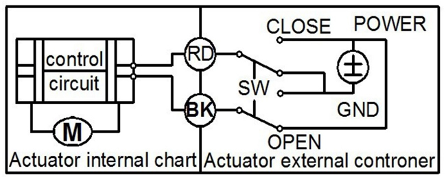
VALVE OPEN: Black wire connect to Positive and Red wire connect to
Negative, valve Open.
VALVE CLOSE: Black wire connects to Negative and Red wire connects to Positive, valve Close.
Remark: When valve fully open/close, power supply to motor will be cutoff automatically by limit switch inside.
Suitable Working Voltage: DC12V/DC24V.
CR2 02 Wiring Diagram (2 wires control – spring return if power failure)
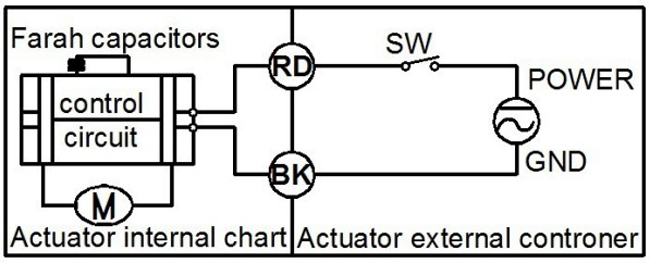
VALVE OPEN: Black wire connect to Negative and Red wire connect to
Positive, valve Open.
VALVE CLOSE: When Red wire disconnects to power/power failure, valve Close.
Remark: When VALVE fully open/close, power supply to motor will be cut off automatically by limit switch inside.
Suitable Working Voltage: AC/DC9-24V, AC/DC110V-230V.
CR3 01 Wiring Diagram (3 wires control)
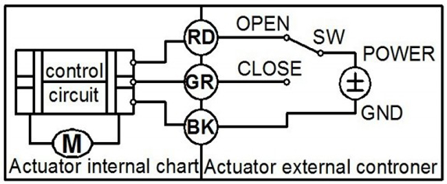
VALVE OPEN: Black wire connect to Negative and Red wire connect to
Positive, valve Open.
VALVE CLOSE: Black wire connects to Negative and Green wire connects to Positive, valve Close.
Remark: When valve fully open/close, power supply to motor will be cut off automatically by limit switch inside.
Suitable Working Voltage: DC12V, DC24V.
CR3 03 Wiring Diagram (3 wires control)
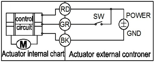
VALVE OPEN: Black wire connect to Negative and Red wire connect to
Positive, meanwhile Green wire connects to Positive, valve Open.
VALVE CLOSE: Black wire connect to Negative and Red wire connect to
Positive, meanwhile Green wire disconnected, valve Close.
Remark: When valve fully open/close, power supply to motor will be cut off automatically by limit switch inside.
Suitable Working Voltage: AC/DC9-24V, AC110-230V.
CR3 04 Wiring Diagram (3 wires control)
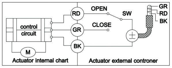
VALVE OPEN: Black wire connect to Negative and Red wire connect to
Positive, valve Open.
VALVE CLOSE: Black wire connects to Negative and Green wire connects to Positive, valve Close.
Remark: When valve fully open/close, power supply to motor will be cut off automatically by limit switch inside.
Suitable Working Voltage: DC12V, DC24V.
CR3 05 Wiring Diagram (3 wires control)
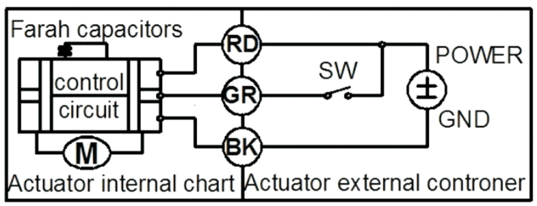
VALVE OPEN: Black wire connect to Negative and Red wire connect to
Positive, meanwhile Green wire connects to Positive, valve Open.
VALVE CLOSE: Black wire connect to Negative and Red wire connect to
Positive, meanwhile Green wire disconnected, valve Close.
Power failure: The Valve CLOSE automatically if power failure.
Remark: When valve fully open/close, power supply to motor will be cut off automatically by limit switch inside.
Suitable Working Voltage: AC/DC9-24V, AC/DC110V-230V.
CR3 06 Wiring Diagram (3 wires control)
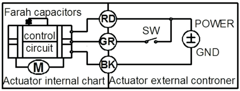
VALVE OPEN: Black wire connect to Negative and Red wire connect to
Positive, meanwhile Green wire connects to Positive, valve Open.
VALVE CLOSE: Black wire connect to Negative and Red wire connect to
Positive, meanwhile Green wire disconnected, valve Close.
Power failure: The Valve OPEN automatically if power failure.
Remark: When valve fully open/close, power supply to motor will be cut off automatically by limit switch inside.
Suitable Working Voltage: AC/DC9-24V, AC/DC110V-230V.
CR4 01 Wiring Diagram (4 wires control)
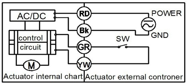
VALVE OPEN: Black wire connect to Negative and Red wire connect to
Positive, meanwhile, White and Yellow wire connected, valve Open.
VALVE CLOSE: Black wire connect to Negative and Red wire connect to
Positive, meanwhile, White and Yellow wire disconnected, valve Close.
Remark: When valve fully open/close, power supply to motor will be cut off automatically by limit switch inside.
Suitable Working Voltage: AC/DC110V-230V.
CR5 01 Wiring diagram (with feedback signal)
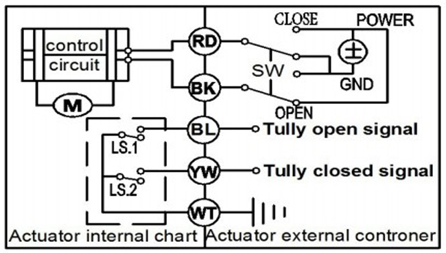
VALVE OPEN: Black wire connect to Positive and Red wire connect to
negative, valve Open.
VALVE CLOSE: Black wire connects to negative and Red wire connects to Positive, valve Close.
When valve fully open, White and Blue wire get through
When valve fully close, White and Yellow wire get through
Remark: When valve fully open/close, power supply to motor will be cut off automatically by limit switch inside.
Suitable Working Voltage: DC12V, DC24V.
CR5 02 Wiring diagram (with feedback signal)
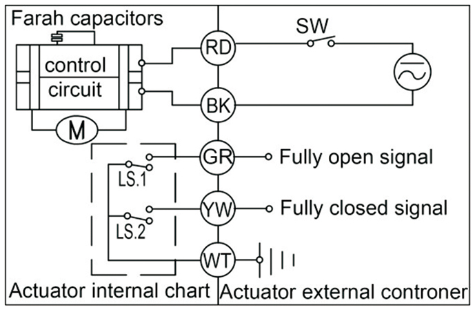
VALVE OPEN: Black wire connects to Negative and Red wire connect to Positive, valve Open.
VALVE CLOSE: When black or Red wire disconnect to power/power failure, valve Close automatically.
When valve fully open, White and Blue wire get through
When valve fully close, White and Yellow wire get through
Remark: When valve fully open/close, power supply to motor will be cut off automatically by limit switch inside.
Suitable Working Voltage: AC/DC9-24V, AC/DC110V-230V.
CR7 02 Wiring diagram (with feedback signal)
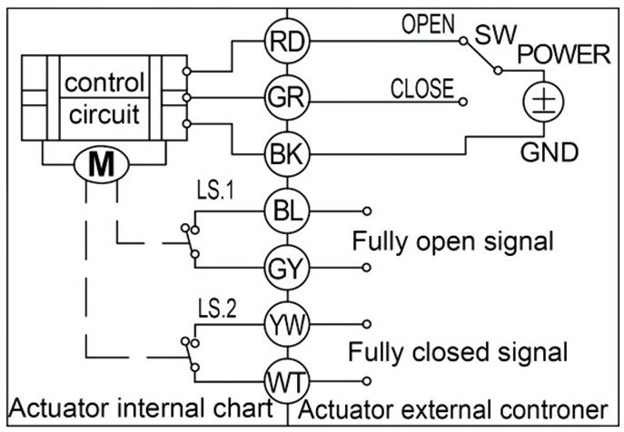
VALVE OPEN: Black wire connects to Negative and Red wire connect to Positive, valve Open.
VALVE CLOSE: Black wire connects to Negative and Green wire connects to positive, valve Close.
When valve fully open, Blue and Gray wire get through
When valve fully close, White and Yellow wire get through
Remark: When valve fully open/close, power supply to motor will be cut off automatically by limit switch inside.
Suitable Working Voltage: DC12V, DC24V.
CR7 03 Wiring diagram (with feedback signal)
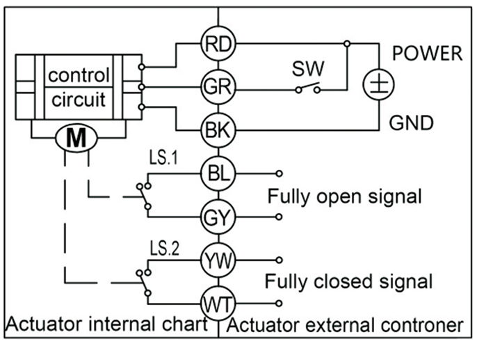
VALVE OPEN: Black wire connect to Negative and Red wire connect to
Positive, meanwhile Green wire connects to Positive, valve Open.
VALVE CLOSE: Black wire connect to Negative and Red wire connect to
Positive, meanwhile Green wire disconnected, valve Close.
When valve fully open, Blue and Gray wire get through
When valve fully close, White and Yellow wire get through
Remark: When valve fully open/close, power supply to motor will be cut off automatically by limit switch inside.
Suitable Working Voltage: AC/DC9-24V, AC110-230V.
CR7 04 Wiring diagram (with feedback signal)
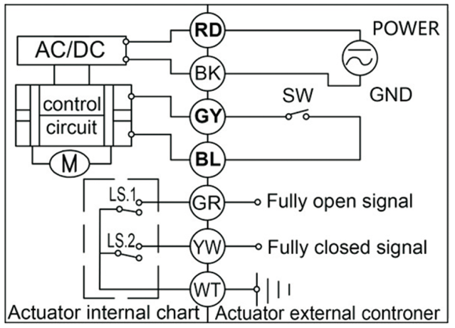
VALVE OPEN: Black wire connects to Negative and Red wire connect to Positive, meanwhile, White and Yellow wire connected, valve Open.
VALVE CLOSE : Black wire connect to Negative and Red wire connect to Positive, meanwhile White and Yellow wire disconnected valve Close.
When valve fully open, White and Green wire get through
When valve fully close, White and Yellow wire get through
Remark: When valve fully open/close, power supply to motor will be cut off automatically by limit switch inside.
Suitable Working Voltage: AC/DC110V-230V.
CR7 05 Wiring diagram (with feedback signal)
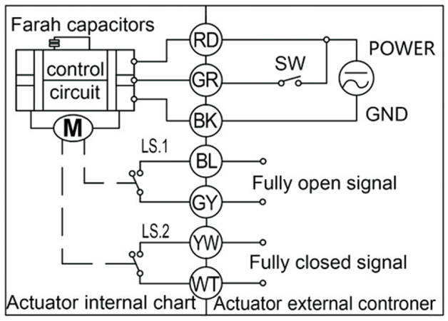
VALVE OPEN: Black wire connect to Negative and Red wire connect to
Positive, meanwhile Green wire connects to Positive, valve Open.
VALVE CLOSE: Black wire connect to Negative and Red wire connect to
Positive, meanwhile Green wire disconnected, valve Close.
Power failure: The Valve CLOSE automatically if power failure.
When valve fully open, Blue and Gray wire get through
When valve fully close, White and Yellow wire get through
Remark: When valve fully open/close, power supply to motor will be cut off automatically by limit switch inside.
Suitable Working Voltage: AC/DC9-24V, AC/DC110V-230V.
CR7 06 Wiring diagram (with feedback signal)
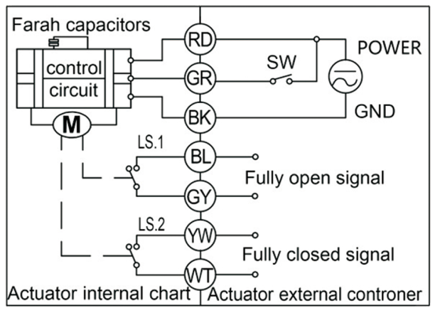
VALVE OPEN: Black wire connect to Negative and Red wire connect to
Positive, meanwhile Green wire connects to Positive, valve Open.
VALVE CLOSE: Black wire connect to Negative and Red wire connect to
Positive, meanwhile Green wire disconnected, valve Close.
Power failure: The Valve OPEN automatically if power failure.
When valve fully open, Blue and Gray wire get through
When valve fully close, White and Yellow wire get through
Remark: When valve fully open/close, power supply to motor will be cut off automatically by limit switch inside.
Suitable Working Voltage: AC/DC9-24V, AC/DC110V-230V.
 Tsai fan Electric Valves wiring diagram.pdf


